
|
|
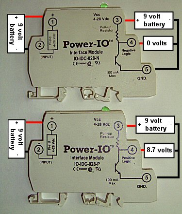
How to quickly
test a Power-io IO-IDC Module, using two 9 volt batteries and a
meter. |
|
|
IO-IDC-028-N or -P generates a logic signal on terminal 4 that is often wired to a PLC's input. The PLC's power supply is wired to terminals 3 and 5. The "-N" model produces a logic signal that is negative compared to the input. (If a field device input exists, no output exists). The "-P" model produces a logic signal that is positive compared to the input. (If a field device input exists, an output exists). When terminal 4 is at 0 volts, it can be used as a sinking signal, at up to 100mA. This is the most common way of using the I/O module. When terminal 4 is "high", then it can be used as a sourcing signal but the mA capability will be limited to a few mA maximum. |
When a control input signal is present on terminals 1 and 2, the logic signal on terminal 4 changes state, and a green LED activates. If the LED is ever red in color, the + and - polarity is probably mis-wired at terminals 3 and 5. Sourcing? Sinking? Here is a quick example of using a sinking signal from an IO module to activate an external product: appnotes/io-module-sinking-example.htm Inverting an input -- making a N.O. signal behave as N.C or a N.O. signal behave as N.C. Normally Closed SSR or Normally Open Sourcing? Sinking? Here is a quick explanation from the internet: http://www.patchn.com |
 |
 |
|
When installed in your application, the Power-io IO modules might be used like this: 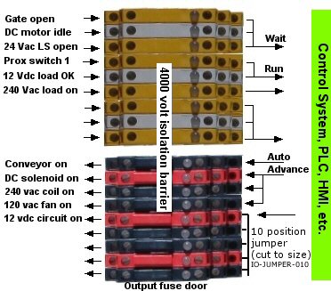 |
The modules can be intermixed as input IO modules and output IO modules:  |
Examples of how to use a variety of IO
modules in an application:
I/O
modules
Return to:
IAC and IDC input
modules or OAC and ODC
output modules