|
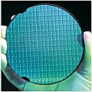 |
HEAT SINKS FOR SOLID STATE RELAY, SCR, and IGBT APPLICATIONSThe switching device inside a modern solid state relay starts as a multi-layer structure of P and N layers grown on a silicon wafer. These become the thyristor dies that are used inside a Power-io solid state relay. The dies are available in different sizes in order to accommodate different amperage capabilities. For example, a die that is approximately 0.25 x 0.25 inches may be the size for a 50 amp application and 0.5 x 0.4 inches might be 125 amps. All solid state relays develop heat as a result of a forward voltage drop through the junction of the die at a rate of approximately 1.2°C per amp that is being switched. Beyond a point, heat will require a lowering (or derating) of the load current that can be handled by the solid state relay. |
 |
Heatsinks are used to create a method of removing heat away from the relay, thus allowing higher current operation. Adequate heat sinks, including consideration of air temperature and air flow, are essential to the proper operation of a solid state relay (SSR, SCR, thyristor or IGBT package). It is necessary that the user provide an effective means of removing heat from the package. The importance of using a proper heat sink cannot be overstressed, since it directly affects the maximum usable load current and/or maximum allowable ambient temperature. Lack of attention to this detail can result in improper switching (lockup) or even total destruction of the solid state relay. Up to 90% of the problems with solid state relays are directly related to heat. POWER-IO has created several customer-specific heatsink designs where overall size, fin geometry, fin angle / spacing, and draw-down geometry were optimized. |
|
With
loads of less than 2-4 amperes, cooling by free flowing convection or forced
air currents around the unit is usually sufficient. Loads greater than 4 Amps
will require heat sinks. SSR units are to be mounted to some heat sinking metal
surface, material heat conductivity should be kept in mind. Heat sinks are
approximately equivalent, in heat dissipation, to a sheet of aluminum 1/8"
thick by the dimensions shown below: 12" X 12" = 288 square inches of exposed surface area = approximately
2.1°C per watt thermal rise (2.1 C/W) (Hint: the lower the C/W rating, the better the heat sink is at dissipating the heat, given proper ventilation and ambient temperature. For example: if a solid state relay generates 45 watts of heat, on a 2.1 C/W heat sink, that relay's internal dies will increase 94.5°C above the ambient temperature. If the ambient is 40°C, the internal die temperature may be 134.5°C.) The maximum permitted temperature for the thyristor die is typically 125°C but 115°C is often used as an additional margin of safety. If air flow is restricted by near by products, or if the ambient air in the enclosure is warmer, of if the solid state relay is not firmly attached to the heat sink, then additional amperage de-rating will be required. Heat Sink Material: The best materials for a heat sink are: gold, silver, copper, or aluminum. For industrial applications, aluminum is the most cost effective material. We typically apply a black anodized finish which provides additional radiant heating dissipation. In comparison to aluminum, twice the amount of steel and four times the amount of stainless steel would be needed to achieve the same effect. Solid state relays should never be mounted in an enclosed area without proper air flow. Units should also never be mounted to a plastic base or to painted surfaces. The heat sink should be positioned with the fins in a vertical position with an unimpeded air flow, up and through the finned heat sink. The interface between the solid state relay and the heat sink must be a flat, clean, bare (non-painted) surface that is free of oxidation. DCB -- Direct copper bonding: The internal thyristor dies are usually soldered to a copper surface on a ceramic substrate. The thin ceramic substrate permits the thyristor's heat to past to the heat sink, while the soft solder surface reduce thermal fatique surrounding the thyristor die area. There is a significant investment in years of Power-io engineering and experience regarding how to create the best DCB assemblies. |
 |
Thermal Pads Silicone thermal transfer grease should be placed on the metal base of the solid state relay before mounting to a metal surface. Heat transfer is affected by the thickness of the thermal compound, uniformity of application and how firmly the relay is attached to the heatsink. We suggest an evenly applied 0.002" thick layer of Dow Corning 340™, or equivalent, and torque of 10 inch-pounds on both of the SSR mounting screws. Note that a thicker layer of thermal compound actually decreases heat transmission. If a dry thermal pad is used, then the mounting screws should be torqued to 20-30 inch-pounds. The black Power-io thermal pad, shown here, provides an optimized layer of high performance thermal compound in a dry pad. |
|
Precautions: Care must be taken when mounting
multiple SSRs in a confined area. SSRs should be mounted on individual
heatsinks whenever possible. Panel mount SSRs should never be operated without
proper heat sinking or in free air as they will THERMALLY SELF DESTRUCT UNDER
LOAD. A simple rule-of-thumb for monitoring temperature is to slip a
thermocouple under a mounting screw. If the base temperature does not exceed 45
°C under normal operating conditions, the SSR is operating in an optimal
thermal environment. If this temperature is exceeded the relay's current
handling ability must either be thermally improved by the use of a heatsink, or
greater air flow must be provided over the device through the use of a fan. ANY
moving air in an installation, greatly improves the thermal transfer from the
heatsink to the air. If the actual internal SSR device ever achieves an
internal temperature of 115 to 125°C, it will be permanently destroyed.
Therefore, the desired engineering requirement is to provide a slow heat-rise
internal SSR, and then to provide a heat sinking capability that draws the
internal heat rise away at a fast rate to ensure that the internal dies do not
exceed these temperatures. Thermal problems are cumulative, irreversible,
and destructive. |
|
|
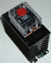
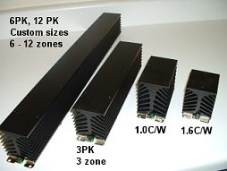
Examples of complete solid state relay assemblies Some cases may require the selection of a higher current output SSR and thermally derating the device accordingly. POWER-IO has specialized in designing SSR packages that optimize the amps vs. thermal rise application. By using a variety of SSR die sizes and copper bonding techniques, we have created packages that generate significantly less thermal rise than is seen in similar packages. Remember that the heat sink removes the heat from the Solid State Relay and transfers that heat to the air in the electrical enclosure. In turn, this air must circulate and transfer its heat to the outside ambient. Providing vents and/or forced ventilation is a good way to accomplish this. Heatsinks should always have at least one inch below them, so air can enter the finned heat sink area. Heatsinks should always have empty space above them so the warm air can exit the heat sink area. If horizontal, plastic, wiring trays are used above the heat sink (such as Panduit™ wiring trays), then the empty space should be greater than the depth of the plastic tray. For example, if you use 4 inch deep wiring trays, leave >4 inches of empty space above the relay. All Power-IO Solid State Relays are capable of running at full rated power (with proper heatsink), however it is strongly suggested that they be used at no more than 80% capacity, at a given temperature, in order to provide a safety margin in case of higher than expected voltage, temperature, dirt on the heatsink, poor air flow, etc. Local electrical codes often require that any design remain below 80% maximum capacity for relays, fuses, wire, circuit breakers, etc, at a given temperature. Caution: Power-IO follows the new international CE testing standard (CE EN60947) that requires testing at 40°C. Other brands of SSRs may follow the older standards that tested at 20 or 25°C. Therefore, some of these other brands may be severely under-rated for your application. |
|
PROTECTIVE MEASURES / ELECTRICAL NOISE SSRs generally do not fail due to electrical noise, unless they happen to mis-trigger during a point in the line cycle when an excessivly high current surge might occur. Usually, a malfunction due to noise is only temporary, such as turning on when the SSR should be off, and vice-versa. By its very nature, noise is difficult to define, being generated by the randomness of contact bounce and arcing motor commutators, etc. Noise, more properly defined as ElectroMagnetic Interference (EMI), affects the SSR by feeding signals into the sensitive parts of the circuit, such as the SCR. A built-in snubber RC network across the output is effective in reducing sensitivity to noise, especially at lower frequencies. |
|
|
MOVs The metal oxide varistor was developed about the same time as the SSR and has subsequently become a trustworthy companion of the SSR, providing much needed protection in some of its more hostile environments. An MOV can be used as follows: across the incoming line to supress external transients before they enter the system; across the load to supress load generated transients; or more frequently, across the SSR to protect it from all transient sources (from L1 to T1). In the latter case, the MOV can be conveniently mounted to the same SSR output terminals as the load wiring. An MOV can be used effectively across such loads as transformers and switching power supplies where spikes too fast to be absorbed by the transformer itself may be fed back into the primary (SSR load) winding. Used within its ratings, the MOV will most likely outlive its associated equipment and provide low cost protective insurance for the SSR. However, an MOV will "wear out" over time if it is constantly exposed to transients. This is why Power-io's Maximum Surge Survival™ technology PLUS an MOV is beneficial since the MOV has three additional surge layers to decrease the transients, thus limiting the quantity and magnitude of the transcients that the MOV is exposed to. Using an MOV is highly recommended when the SSR is used as a motor starter OR if nearby motor starting and stopping occurs on the same power line that the SSR is on. For a picture of the proper installation of a MOV under our finger-safe protective cover, see: motor starters. There are several manufacturers of MOVs including Littlefuse Harris |
|
SURGE RATINGS There are very few completely surgeless SSR loads. Next to improper heatsinking, surge current is one of the most common causes of SSR failure. Overstress of this type can also seriously impair the life of the SSR. Therefore, in a new application, it would be wise to carefully examine the surge characteristic of the load and then select a device that can adequately handle the inrush as well as the steady state condition, while also meeting the lifetime requirements. In addition to the actual surge ratings given for SSR's, the rate of rise of surge current (di/dt) is also a factor in AC thyristor types. Exceeding its value may result in destruction of the device. As a guide, the amperes-per-microsecond (di/dt) withstand capabilities are typically in the order of their single cycle surge ratings. The highest surge current rating of an SSR is typically 10 times the steady-state RMS value, and it is given as the maximum peak current for one line cycle. It should be noted that a surge of this magnitude is allowable a limited number of times, such as only 100 times during the SSR's lifetime. Furthermore, control of conduction may be momentarily lost due to a surge. This means that it may not be possible to turn off the SSR by removal of control power both during and immediately after the surge. The output thyristor must regain its blocking capability and the junction temperature allowed to return to its steady state value before reapplication of the surge current, which may take several seconds. It should be noted that the preceding cautionary notes apply only to the extreme limits where the SSR should not be designed to operate anyway. Generally, DC switching SSRs do not have an overcurrent surge capability, since the output transistors are usually rated for continuous operation at their maximum capacity. The tendency is for the DC SSR to cut off (current limit), thus impeding the flow of excessive current. However, the resultant overdissipation may destroy the relay if the surge is prolonged. |
 |
I²T FUSING Fast, "Semiconductor Fuses" are the only reliable way to protect solid state relays. They are also referred to as current-limiting fuses, providing extremely fast opening (about 2 msec) while restricting let-through current far below the fault current that could destroy the semiconductor. This type of fuse tends to be expensive, but it does provide a means of fully protecting SSRs against rapid rise, high current overloads where survival of the SSR is of prime importance. An I²T fuse rating (ampere-squared seconds) is useful in aiding in the proper design of SSR fusing. This rating is the bench mark for an SSRs ability to handle a shorted output condition. Power-io advocates SSR protection through the use of a properly selected I²T (semiconductor) fuse. Devices such as electromechanical circuit breakers and slow blow fuses cannot react quickly enough to protect the SSR in a shorted condition and are not recommended for SSR protection!!! Fast blow type fuses may be appropriate for some applications. Every SSR has an I²T rating (see SSR specifications on this web site). The procedure is to select a fuse with an I²T let-through rating that is less than the I²T capability of the solid state relay for the same duration. I²T relates directly to the published fuse characteristics. System designers who are considering using I²T fuses should consult a good technical manual dealing with the application of these fuses when designing their systems (i.e. Cooper Bussman's semiconductor fuse catalog). For wiring protection and installation protection, you must continue to use standard circuit breakers or standard fuses in accordance with local electrical codes. |
|
SSR APPLICATIONS Solid State Relays (SSRs) cannot always be applied in exactly the same way as Electromechanical (EMRs) and when such is the case, caution should be taken. Inductive Loads While most solid state relay loads, even lamps, include some inductance, its effect with resistive loads is usually negligible. Only those loads that utilize magnetics to perform their function, such as transformers, chokes (windings), or coils are likely to have any significant influence on SSR operation. These loads can create large current surges and the SSR should be derated accordingly. ***Please call Technical Support for additional Suggestions. Transformer Switching Extremely high current surges are commonly associated with transformers, especially those with a penchant for saturation. The zero voltage turn on feature of standard SSRs can increase this possibility and might require that special precautions be taken. The zero current turn off characteristic of SSRs, while minimizing the problem, will not prevent it. From the practical and economic standpoint, the best choice may still be a standard SSR, overrated to withstand huge surges. ***Please call Technical Support for additional Suggestions. Motor Switching Dynamic loads such as motors and solenoids, etc., can create special problems for solid state relays. High initial surge current is drawn because their stationary impedance is usually very low. As a motor rotates, it develops a back EMF that reduces the flow of current. This same back EMF can also add to the applied line voltage and create 'overvoltage' conditions during turn off. Most of the surge reducing techniques discussed earlier can also be applied to motors. It should be noted that overvoltage caused by capacitive voltage doubling or back EMF from the motor cannot be effectively dealt with by adding voltage-transient suppressors. Suppressors such as Metal Oxide Varistors (MOVs) are typically designed for brief high voltage spikes and may be destroyed by sustained high energy conduction. It is therefore important that SSRs are chosen to withstand the highest expected sustained voltage excursion. ***Please call Power-io's Technical Support for additional Suggestions. Lamp Switching The inrush current characteristic of incandescent (tungsten filament) lamps can be 10 times steady amperage conditions, during a cold start. A solid state relay needs to be sized to be able to withstand those inrush conditions. CAUTION: Using SSRs for driving mercury, fluorescent, or HID lamps should be based upon the documented inrush of those applications. The SSR must be properly rated and thoroughly tested in the specific application. ***Please call Power-io's Technical Support for additional Suggestions. |
|
Power-io
537 Braemar Avenue Naperville, IL 60563
USA |